


Send Message
Privatsphär Ausso: Är Privatsphär ass ganz wichteg fir eis. Eis Firma versprécht Är perséinlech Informatioun un all Expany mat all explizit Permissiounen ze verroden.
Model No.: NSO4GU3AB
Transport: Ocean,Air,Express,Land
Bezuelungsart: L/C,T/T,D/A
Incoterm: FOB,EXW,CIF
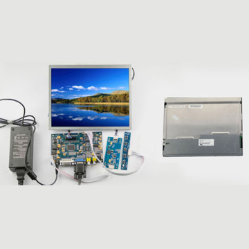
4GB 1600mhz 240-PIN DDR3 UDIMM
Fräibositioun
|
Revision No. |
History |
Draft Date |
Remark |
|
1.0 |
Initial Release |
Apr. 2022 |
|
![]()
Fir Informatiounsdësch bestellen
|
Model |
Density |
Speed |
Organization |
Component Composition |
|
NS04GU3AB |
4GB |
1600MHz |
512Mx64bit |
DDR3 256Mx8 *16 |
Broessdatsch
Hengstar Onbuffed DDR3 SDRAM DIMMS (OBUPUFFED DUBUFFE PRESSION SYNCONOUS DRUAL INCAL INDIAL INCALT Memory Corder, héich-Geschwindegkeetsverbänn. NS04Gu3ab ass e 512M x 64-Bit zwee Rang 4GB DDR3-1600 CLA11 1.5V SDRABUFFT DIMM CLONECTEKT CHOMME MIMPERSULS04GUU3BUACUACE ass e 512M x 64-Bit zwee Rang 4GB DDRR3-1600 CLA11 1.5V SDRAK UMPUFFED DIMMT MIMT MIMT MIMT MIMT MIMT MIMT MIMPTENTE MIMPTEND MIMPTENS. AMMSTON CHONTEN MIMPTEND MIMPTENDEN. De Spd ass programméiert fir Jedec Standard Latency DDR3-1600 Timing vun 11-11-11 am 1.5V. All 240-Pin Dimm benotzt Gold Kontakt Fanger. D'SDRAM Onbuffed Dimm ass geduecht fir ze benotzen als Haaptchroch wann et a Systemercher installéiert ass wéi PCSstatiounen.
Eegeschaften
ower Versuergung: VDD = 1.5V (1.425V bis 1,575V)
39.5v (1.425v bis 1,575V)
800mhz FCK fir 1600MB / Sec / PIN
Aner onofhängeg intern Bank
Fir
¡Programméierbar Zouschungsverkince: 0, Cli - 2, oder CL - 1 Auer
58-Bit Pre-Fetch
Sophurst Längt: 8 (Interleve ouni Limit, Sequenz mat Startadress "000" nëmmen), 4 mat tCCD = 4 wat net erlaben ze liest (entweder op der Plaz
Direktuell Differenzial Date Stroll
Shovein (Selbst) Kalibratioun; Intern Selbst Kalibratioun duerch Zq Pin (RZQ: 240 ohm ± 1%)
an stierwen Oflagerung mat Hëllef vun OdTT PIN
aanagrage erfrëscht Period 7.8us am Einfache wéi de Strahlen 85 ° C, 3.9us op 85 ° C <95 ° C
√atynnchronous zréckgesat
adjustable Daten-Output Drive Stäerkt
vun der Topologie
Papcb: Héicht 1.18 "(30mm)
Forms konform an halogen-gratis
Key Timing Parameteren
|
MT/s |
tRCD(ns) |
tRP(ns) |
tRC(ns) |
CL-tRCD-tRP |
|
DDR3-1600 |
13.125 |
13.125 |
48.125 |
2011/11/11 |
Den Adressautett
|
Configuration |
Refresh count |
Row address |
Device bank address |
Device configuration |
Column Address |
Module rank address |
|
4GB |
8K |
32K A[14:0] |
8 BA[2:0] |
2Gb (256 Meg x 8) |
1K A[9:0] |
2 S#[1:0] |
Pin Beschreiwunge
|
Symbol |
Type |
Description |
|
Ax |
Input |
Address inputs: Provide the row address for ACTIVE commands, and the column |
|
BAx |
Input |
Bank address inputs: Define the device bank to which an ACTIVE, READ, WRITE, or |
|
CKx, |
Input |
Clock: Differential clock inputs. All control, command, and address input signals are |
|
CKEx |
Input |
Clock enable: Enables (registered HIGH) and disables (registered LOW) internal circuitry |
|
DMx |
Input |
Data mask (x8 devices only): DM is an input mask signal for write data. Input data is |
|
ODTx |
Input |
On-die termination: Enables (registered HIGH) and disables (registered LOW) |
|
Par_In |
Input |
Parity input: Parity bit for Ax, RAS#, CAS#, and WE#. |
|
RAS#, |
Input |
Command inputs: RAS#, CAS#, and WE# (along with S#) define the command being |
|
RESET# |
Input |
Reset: RESET# is an active LOW asychronous input that is connected to each DRAM and |
|
Sx# |
Input |
Chip select: Enables (registered LOW) and disables (registered HIGH) the command |
|
SAx |
Input |
Serial address inputs: Used to configure the temperature sensor/SPD EEPROM address |
|
SCL |
Input |
Serial |
|
CBx |
I/O |
Check bits: Used for system error detection and correction. |
|
DQx |
I/O |
Data input/output: Bidirectional data bus. |
|
DQSx, |
I/O |
Data strobe: Differential data strobes. Output with read data; edge-aligned with read data; |
|
SDA |
I/O |
Serial |
|
TDQSx, |
Output |
Redundant data strobe (x8 devices only): TDQS is enabled/disabled via the LOAD |
|
Err_Out# |
Output (open |
Parity error output: Parity error found on the command and address bus. |
|
EVENT# |
Output (open |
Temperature event: The EVENT# pin is asserted by the temperature sensor when critical |
|
VDD |
Supply |
Power supply: 1.35V (1.283–1.45V) backward-compatible to 1.5V (1.425–1.575V). The |
|
VDDSPD |
Supply |
Temperature sensor/SPD EEPROM power supply: 3.0–3.6V. |
|
VREFCA |
Supply |
Reference voltage: Control, command, and address VDD/2. |
|
VREFDQ |
Supply |
Reference voltage: DQ, DM VDD/2. |
|
VSS |
Supply |
Ground. |
|
VTT |
Supply |
Termination voltage: Used for control, command, and address VDD/2. |
|
NC |
– |
No connect: These pins are not connected on the module. |
|
NF |
– |
No function: These pins are connected within the module, but provide no functionality. |
NOTIZEN : De Pin Beschreiwung Table One ass eng ëmfaassend Lëscht vun all méiglechen Pins fir all DDR3 Moduler. All Pins opgezielt kënne sinn net op dësem Modul ënnerstëtzt ginn. Gesinn PIN Uerderen fir Informatiounspositioun fir dëse Modul.
Funktional Block Diagramm
4GB, 512Mx64 Modul (2rank vun x8)


Modul Dimensiounen
Frann Vue

Frann Vue

Notizen:
1.ALL Dimensiounen sinn an Millimeter (Zoll); Max / min oder typesch (Typ) wou bemierkt.
2.Tolerance op all Dimensioune ± 0,15mm wann anescht anescht uginn.
3.Dhe dimensional Diagramm ass nëmme fir Referenz.
Produkter Kategorien : Industriell Smart Modul Accessoiren


Privatsphär Ausso: Är Privatsphär ass ganz wichteg fir eis. Eis Firma versprécht Är perséinlech Informatioun un all Expany mat all explizit Permissiounen ze verroden.
Fëllt méi Informatioun aus fir datt dat méi séier a Kontakt kënnt
Privatsphär Ausso: Är Privatsphär ass ganz wichteg fir eis. Eis Firma versprécht Är perséinlech Informatioun un all Expany mat all explizit Permissiounen ze verroden.